Instrumented Uneven Walkway (IUW)
Senior Design Project
Team Lead
August 2024 - May 2025
The Problem
Researchers at Virginia Tech and James Madison University are interested in using an adjustable sloped walkway to study inclined walking along two axes to replicate real-world environments.
Existing solutions lack portability, have a fixed slope, and cannot provide bidirectional tilt.

An existing walkway with a lateral tilt.
During this two-semester long senior design project, I was selected as Team Lead. I learned how to adapt project needs to varying timelines and constraints and how to maintain effective communication.
The Process
01. Research Existing Solutions
04. Standards and Statutory Requirements
07. Product Requirements
10. CAD Modeling
13. Functional Prototype Construction
02. System and Gap Analysis
05. Design Constraints
08. Preliminary Hazard Analysis
11. Risk Analysis (FMEA)
14. Verification and Validation Testing
03. User Needs
06. Ethical and Professional Responsibilities
09. Proof-of-Concept, Concept Selection, and Budgeting
12. Simulations in COMSOL
15. Final Product Delivery
User Needs


Concept Generation
.png)
In the functional decomposition for the IUW's intended function during use, blocks represent technical functions and different lines represent flows of energy, materials, and signals.
.png)
The morphological chart presents solution options for the IUW's functions and components. Functions and components occupy the rows whereas solution options are reflected in the columns.
Initial Concept Sketches
 |  |  |
|---|---|---|
 |  |  |
Final Concept
.png)
The final concept uses a combination of ideas from the morphological chart and initial concept sketches.
We had a $1500 budget to work with to build the 15-foot long portable walkway. This constraint was a big contributor to our solution design.
CAD Modeling

Full assembly of the IUW, modeled and detailed within a SolidWorks drawing

Platform subsystem of the IUW

Scissor jack subsystem of the IUW

Farm jack subsystem of the IUW
Computational Load Testing Using COMSOL
One design decision we still hadn't made was how many support legs should go underneath the walkway surface. I designed a study in COMSOL to answer the question.
What is the minimum number of support legs needed to maintain a factor of safety (FoS) of at least 2?
I conducted FEA on a simplified version of the IUW, shown below.

Placement of footstep areas tested in COMSOL, where each area is the size of a 50th percentile male foot.

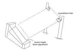
View of the model assessed in COMSOL with labeled constraints. The goal was to simulate loading from a single footstep as someone walks across the IUW surface.

Results from 80 COMSOL simulations.
With four support legs, the minimum FoS (excluding the counterbore constraint area) consistently exceeds 2 across all simulations. However, when the counterbore constraint area was included in calculations for the flat orientation, the FoS dropped below 2 (at step ID 1). The team did not consider this a critical issue, as the constraints applied in COMSOL do not accurately reflect real-world IUW configuration due to model simplification. We reinforced the counterbore holes with a metal plate on the underside of the connection point and a metal washer on the top side of the connection point in the real prototype.
The class computational requirement only would have only required me to put one downward force on the model, but I wanted to do extensive and thorough testing before moving forward.
Prototype Construction


Early stage prototypes to assess tilt adjustment capabilities.
 |  |  |  |
|---|---|---|---|
 |  |  |  |
 |  |  |  |
 |  |  |  |
Scroll through to see our build phase highlights!
During the process we had lots of design changes and things that didn't work as expected. We were able to engineer new ideas quickly and had lots of laughs along the way. This project made me realize how fun it is to step away from coding and tackle hands-on tasks. This project caused me to step out of my comfort zone; I learned how to use power tools, how to come up with new solutions quickly, and most importantly that a 15 foot walkway is a lot bigger in real life than it seems on the computer!

It all ended in a successful showcase!
Final Showcase Poster

Special thanks to Ella Tomko, Lauren Mulligan, Lee Edwards, and Yelu Zhao for their teamwork on this project, and thanks to Dr. Chris Arena, Dr. Robin Queen, and Dr. Wunderlich for their mentorship and guidance throughout this project.